Getting Started
If you read this page, you're probably one of the very few beta-testers who have a "Qualification Sample" UCA in hand. Congratulation and thanks for your time! Your feedbacks are very helpful to finalize the design. The UCA has been designed to be easy to use. The basic procedure is quite simple, but must be followed strictly to avoid any issues:
- Put the switch OFF (left)
- Configure the "CHIP ID" RED dipswitch (top-right) according to the IC you want to test
- Configure the "CONFIG" BLUE dipswitch (bottom-left) with the optional settings
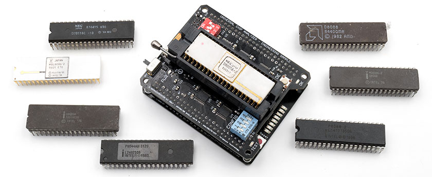
- Plug the IC into the Socket and pull the lever down to lock it in place
- Put the switch ON (right)
If all goes well, the red PWD LED should lit and the testing sequence begins. If the blue OK LED is lit, the IC is working properly. Repeat from 1. for every tested IC. DO NOT change any settings on the DIP Switches when an IC is plugged or the UCAS is powered on !
WARNING: make sure you selected the correct CHIP ID before inserting a component!
You will find two push buttons on the iAPX-86 UCAS. The first one (RED) is located near the LEDs. It resets the DUT (Device Under Test) inserted into the Socket. The second button (BLACK) is labelled "MODE". Right now, it only show specific features while testing 8088/8086.
Configuration
You can insert an IC and switch the power on as soon as CHIP ID and CONFIG buttons are configured properly. Please note that CONFIG settings are dependent of the CHIP ID selected! The meaning of CONFIG bits is different for every different CHIP ID.
Here are the current settings available:
 |
Select Intel 8086/8088 Family Also supports NEC V20/V30 & pin-compatibles IC Available testing frequencies : 4 / 6 / 8 / 12.5 MHz |
 |
Select Intel 8085 Family Also supports any pin-compatible CPU. Available testing frequencies : 6 / 8 / 10 / 12 MHz |
 |
Select Intel 8080 Family *ADAPTER REQUIRED* Also supports AMD 9080 and any pin-compatible CPU. Available testing frequencies : 2.0 / 2.6 / 3.4 / 4 MHz |
 |
Select Zilog Z80 Family *ADAPTER REQUIRED* Also supports any pin-compatible CPU. Available testing frequencies : 2.5 / 5 / 6 / 8 MHz |
 |
Select National Semiconductors NSC800 Family Also supports any pin-compatible CPU. Available testing frequencies : 4 / 10 / 12 / 16 MHz |
 |
Select Intel MCS-48 (8048) Family Also supports 8035/38/39/40/49/50 & 8748/49/50. Available testing frequencies : 6 / 8 / 11 / 12 MHz |
 |
Select Intel MCS-51 (8051) Family Also supports 8031/32/44/52 & much more Available testing frequencies : 8 / 12 / 24 / 40 MHz |
 |
Select Signetics 2650 Family *ADAPTER REQUIRED* Also supports any pin-compatible CPU. Available testing frequencies : 1.25 / 2 / 2.5 / 3 MHz |
 |
Select RCA CDP1802/COSMAC Family Also supports any pin-compatible CPU. Available testing frequencies : 2.5 / 3.2 / 4 / 5 MHz |
 |
Select MOS 6502 Family *ADAPTER REQUIRED* *Alpha* Currently supports 6502 only. Available testing frequencies : 1 / 2 / 3 / 4 MHz |
 |
Select Motorola 6800 Family *ADAPTER REQUIRED* *Alpha* Currently supports 6800 only. Available testing frequencies : 1 / 1.5 / 2 / 3 MHz |
Please configure CONFIG dip switches according to the CHIP ID you just selected. The two first switches are used to set the testing frequency. The available frequencies available are listed on the previous table. The third switch enables the burn-in mode (only 8088/8086 now) and the fourth switch is reserved for future uses. Switches 1 & 2 are linked together but Switches 3 & 4 are independent.
For example, here are the CONFIG settings for the 8086 Family:
 |
4 MHz Frequency Slowest frequency available (8086-4) First frequency listed in the CHIP ID table |
 |
8 MHz Frequency A very common frequency (8086-2) Second frequency listed in the CHIP ID table |
 |
10 MHz Frequency Another very common frequency (8086-1) Third frequency listed in the CHIP ID table |
 |
12.5 MHz Frequency Overclocking or some NEC V20/V30 Fourth frequency listed in the CHIP ID table |
 |
Burn-In Mode Enable Perform much longer tests Only available on 8086/8088 yet (soon for other ICs) |
 |
Reserved Feature TBD Upcoming Benchmark mode? |
MODE Button
When pressed, the MODE button temporarily displays a binary code. It will be used in the future to show detected features when the UCA is used as a standalone tester. Right now, it only works with the 8088/8086 firmware. Here are a preliminary table (Firmware 0.9 - LEDs from left to right):
- LED7: 8018x Microcode
- LED6: NEC Microcode
- LED5: Harris/Intersil Microcode
- LED4: Intel '81 Microcode
- LED3: Intel '78 Microcode
- LED2: TBD
- LED1: TBD
- LED0: 16-bit bus detected
For example, if you have LED3 & LED0 lit when you press the MODE button, your CPU is detected as an Intel 8086 (16-bit) with a '78 (very early) microcode. If only LED6 is lit, you have a NEC-based CPU microcode with a 8-bit bus (NEC V20).
Advanced Analysis / Tethered Mode
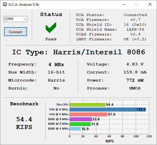
Advanced Analysis – only available when the UCA is plugged (USB) – is still in very alpha stage. It will allow to retrieve more diagnostic details about the DUT (Device Under Test) like Power Consumption, Process, Microcode, Performance (benchmarks), etc. The UCA companion software will also display many information about the UCA itself (embedded firmware revisions, …).
The UCA doesn't require any specific drivers when plugged on Windows 10 64-bit
UCAS Firmware Upgrade
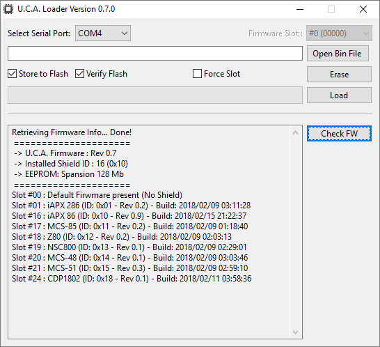
UCAS Firmware updates are required to support new IC families (and also to solve bugs or add features on already-supported IC). The 128 Mbit Flash EEPROM embedded on the UCA can support up to 42 different UCAS firmwares. Each of them is linked to a specific CHIP ID. A tool – the UCA Loader – is provided to deal with firmware updates:
Many features are reserved for development and should not be used by beta-testers. Here is the basic process to upload new UCAS firmware into the UCA.
Launch the application then select the COM port used by your UCA. Click "Check FW". You should see a complete list of all installed firmwares, with their revision, slot number and build date. To update an UCAS firmware, click on "Open Bin File" and select the new .bin file. The corresponding Slot Firmware should be autodetected. Make sure both "Store to Flash" and "Verify Flash" are checked, and "Force Slot" is unchecked, then click "Load". After ~30 seconds, the UCAS Firmware should be updated/loaded successfully.
Download
Some files required for beta-testers. More to come.
- UCA Loader v0.5b (53.1 MB - Sorry for that...)
- iAPX-86 UCAS (Slot #16) - 8088/8088 FW: Rev 0.9 Beta 2 - Build: 2018/02/15 21:22:37 (333 KB)
- iAPX-86 UCAS (Slot #24) - RCA CDP1802 FW: Rev 0.1 Beta 1 - Build: 2018/02/11 03:58:36 (333 KB)
- iAPX-86 UCAS (Slot #25) - MOS 6502 FW: Rev 0.1 Beta 2 - Build: 2019/06/02 16:19:30 (333 KB)
Troubleshooting
Things going wrong? Here are some tips to solve known issues. Keep in mind that UCAS Firmware are still in very early stages. Many debug features are still present. Firmware must be considered experimental below Rev 0.5 and unstable below 0.9.
Before trying anything else, make sure that you use a good quality, short USB cable. An external USB battery bank is the best way to power the UCA, but any USB port from a motherboard should provide enough power. Try to unplug/replug the USB cable and wait 5 seconds before powering the Shield if something goes wrong.
95% of issues I encountered while developing the UCAS came from an unreliable contact between the IC and the ZIF Socket. Make sure that pins are clean, perfectly aligned and not bent in any ways. Some thin white ceramic ICs (like USSR 8086 clones) require the small plastic interposer between the IC and the Socket (you got one). Try to unlock the chip, move it slightly then lock it again, that will solve almost all issues.
WARNING: if the red PWR LED does NOT lit after the UCAS is switched on, switch it OFF immediately: a short-circuit (or overcurrent) has been detected.