Another milestone – albeit not the hardest one – has been reached! The 80286 is the 2nd gen 16-bit x86 CPU introduced by Intel in 1982. The most important improvement was the use of a separated data and address bus. Its predecessor, the famous Intel 8086, used the same pins to send address and then data. The lack of that slow time-multiplexed bus on the 286 allowed a major performance boost, sometimes more than 100% at a similar clock speed. The microarchitecture also evolved with a more advanced (dedicated) address calculation unit and a faster multiplier. The 80286 was also able to support up to 16 MB of RAM, thanks to its 24-bit address bus.
The 80286 also introduced the protected mode, designed to allow much more advanced memory management, with the ability to build multi-user systems using multitasking applications. Unfortunately, due to several limitations in that first implementation, along with several hardware errata found in earlier stepping, protected mode wasn’t really used by software developers on the 286. Intel only solved all these issues with the 80386. The Intel 80286 was initially released at 4, 6 and 8 MHz on nMOS 1.5 µm process. Later released reached 12.5 MHz in 1 µm CMOS process. Several other companies produced CPU fully based on Intel’s 286 microcode like AMD, Siemens and Harris, with speed up to 25 MHz!
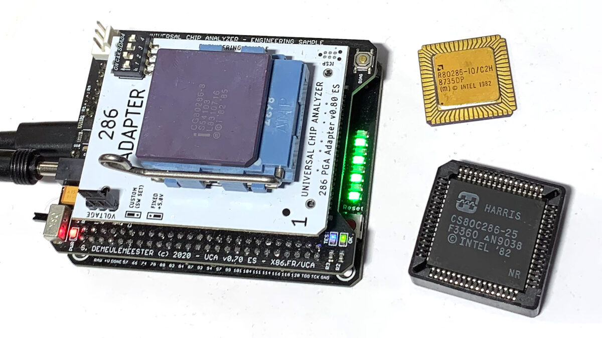
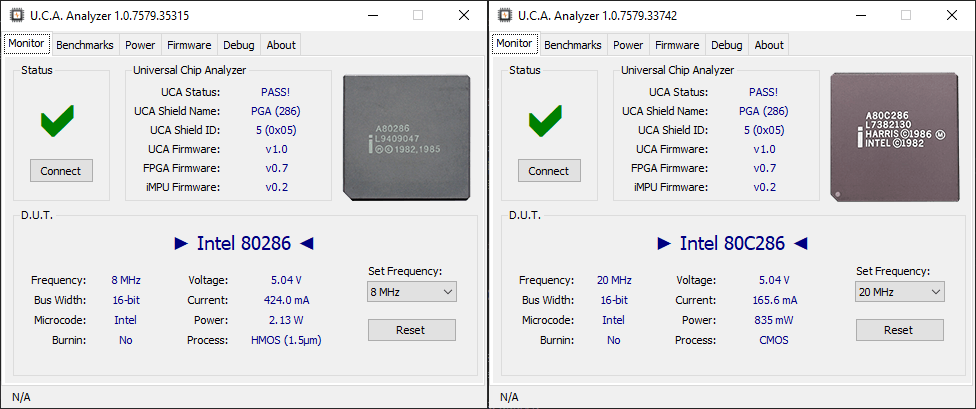
Three common 68-pin packages were used for the vast majority of the 80286s ever produced: the original ceramic PGA, a leadless LCC (also ceramic) and a plastic PLCC. On the picture above, you can see an AMD R80286-8 (LCC) and a Harris CS80C286-25 (PLCC). The Universal Chip Analyzer is able to test all three packages just by plugging the related socket on the PGA DIP Socket. Frequencies available (by DIP Switches or software) are 4, 8, 10, 12.5, 16 and 20 MHz.
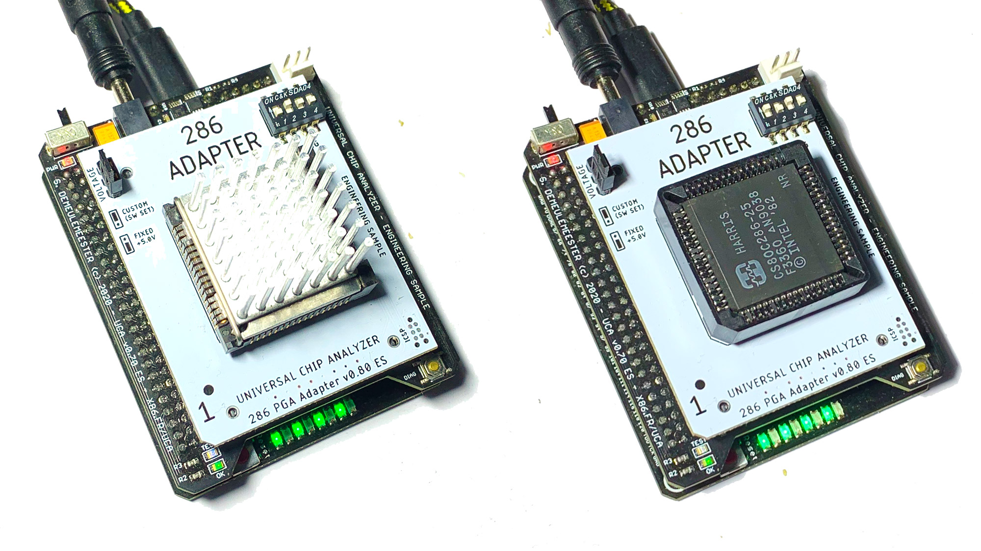
 Why not 25 MHz? Because the 80286 requires a clock-doubled input and feeding a 50 MHz clock to get the 25 MHz core frequency would have required an external PLL. Not a big deal, but there is only one rare 286-class CPU that supports this frequency (the Harris/Intersil CS80C286-25 pictured above) and its timings is not fully compliant with the 286 specifications. Designing a special UCA adapter just for this chip is trivial, but quite useless because the 286 Adapter is already able to test it at 20 MHz. Speaking about “high” frequencies, using the right socket is crucial
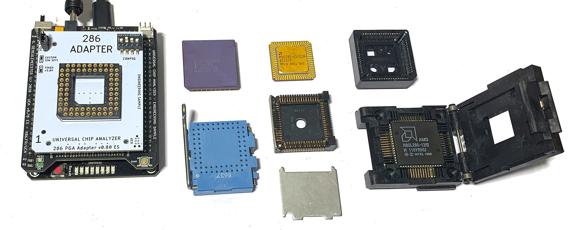 The UCA 286 Adapter is fitted with a high-quality DIP Socket. Directly plugging a PGA 286 CPU is possible but not convenient for testing multiple CPUs in a row. I was able to secure some ZIF Sockets for 68-pin PGA like the blue one pictured here (from AMP) and also some 3M LCC sockets complete with top cap. About PLCCs, I first tried some cheap socket from eBay. That was a disaster: contact pins were too weak and bent after 2-3 insertions. Worst, the maximum frequency allowed was 8-10 MHz. Replacing these crappy sockets with other ones from Foxconn or 3M solved all the issues. I also bought some awesome Yamaichi test Socket for PLCC (on the right), but unfortunately, they use a specific pinout. As the 286 Adapter uses a simple 2-layer PCB, I will consider designing a specific PCB just for them.
With the hardware finished, I’ll later tune the software-testing code to see if I can detect various stepping, and maybe also the manufacturer.