While designing the ATX2AT Smart Converter (and especially when I did the modifications after the Kickstarter campaign – I’ll write about them later), I had to study how negative voltage (-12V & -5V) are used to implement everything correctly.
-12V is not really a problem: this power rail is still available in the current ATX Specification. I tried and measured current consumption on many motherboards and ISA cards to finally decide to protect the rail with a 500 mA resettable fuse (PPTC).
Generating the -5V rail needed by some ISA cards was a bigger challenge to properly size the components. Basically, there is two methods to get -5V from a modern ATX PSU:
- DC-DC converter. It can deliver tremendous power (several amps) on a -5V rail converted from +12V or +5V. But it has drawbacks: DC-DC Converter are electrically noisy. It also requires more components and are most expensive.
- Linear Regulator. It derives -5V from -12V by converting the unneeded voltage (7V here) to heat. Linear Regulator doesn’t generate electric noise and are quite cheap these days. Its major drawback is the heat they generate, which limit the maximum current they can deliver.
Should I go for a DC-DC Converter scheme and get a noisier current at a higher cost (in order to get more current), or stay with a linear regulator? It was time to study the needs.
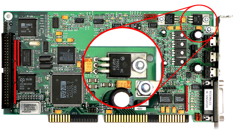
A lot of old ISA cards requires -5V internally. Many of them integrate their own 7905 linear regulator and don’t use the -5V rail provided by the power supply through the motherboard. For example, the Media Vision Pro Audio Spectrum 16 (PAS16) is one of them: you can see the 7905 on top left of the board.
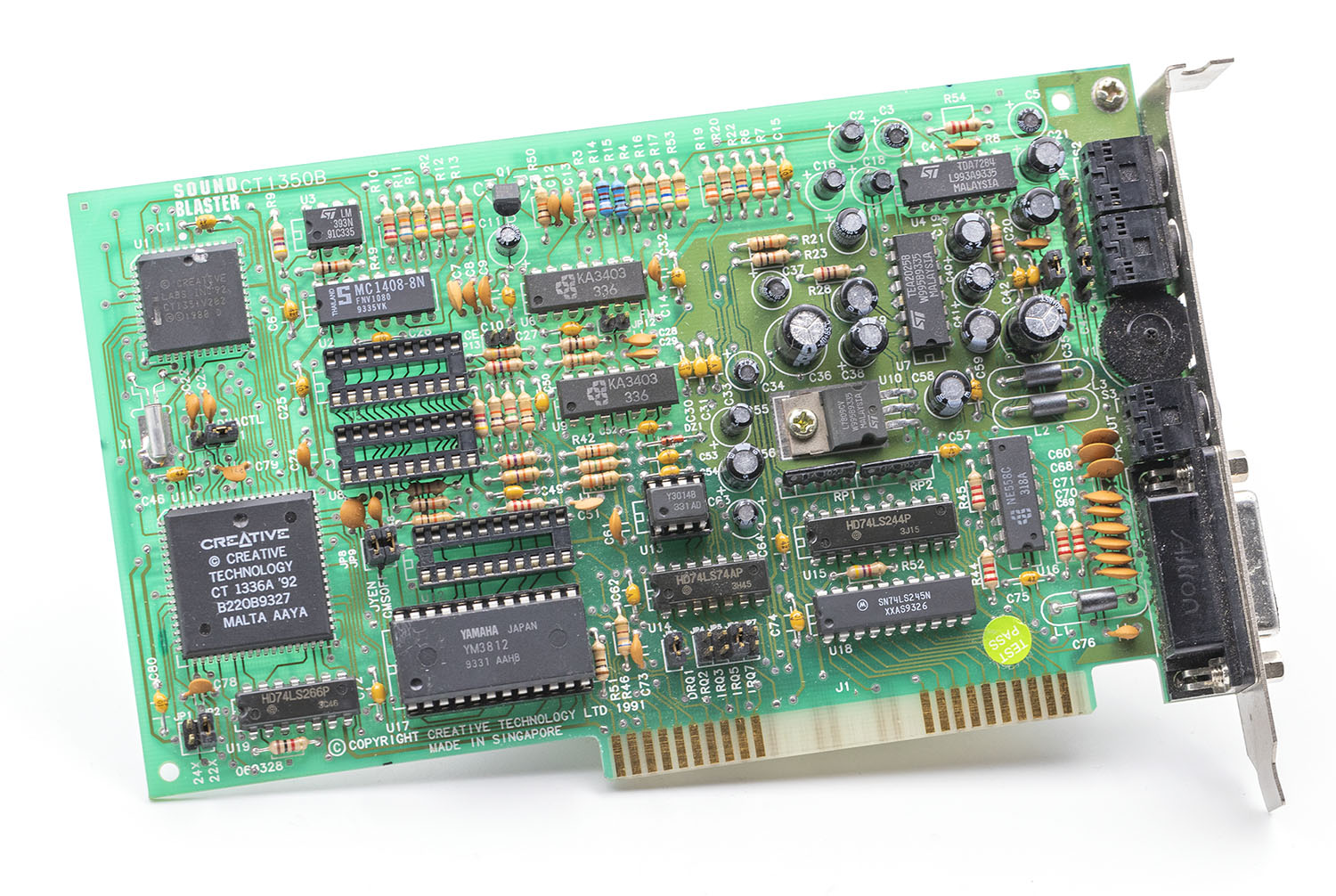
 But many boards rely on the -5V provided by the PSU. One of them is the famous Sound Blaster 2.0 (CT1350) :
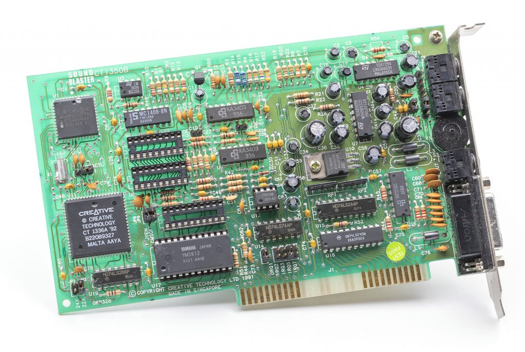
But what is the -5V used for? In all the ISA Card I studied, the -5V is used for the same stage: preamp. Basically, a sound card generates an analog signal from a digital bus with a DAC (Digital to Analog Converter). On the picture above, the DAC is the tiny IC in the center of the board marked “Y3014B”. It’s a Yamaha YM3014B. The output signal from this DAC is very weak and must be amplified before reaching speakers.
First, the analog from the DAC is preamplified with the two ICs marked KA3403 just above him. It’s a signal conditioning stage only. They are simple low-power operational amplifiers used to boost the voltage amplitude of the DAC signal to a bigger one. But in order to connect speakers, you need a much higher current/power capability. So the signal is then fed to a power amplifier: the ST TEA2025B located on the right of the board. This schematic is very common and used in almost all ISA sound cards.
-5V is only required for the KA3403s (the preamplifier stage). The datasheet available here tells us the output load is spec’ed at 2K Ohm so each KA3403 can output 2.5 mA x 4 opamp = ~10 mA. We have two of them and let’s add the power supply current (spec’ed at 7 mA max) and the Sound Blaster 2.0 will never need more than 2 x (10+7) = 34 mA on the -5V. That’s an absolute maximum in a worst-case scenario. Actually, the “typical” power supply is 2.8 mA and the load is much higher than 2K Ohm.
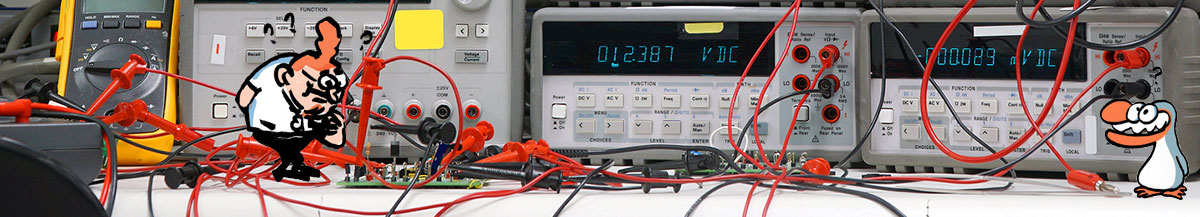
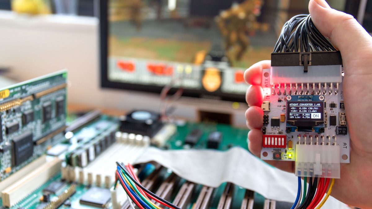
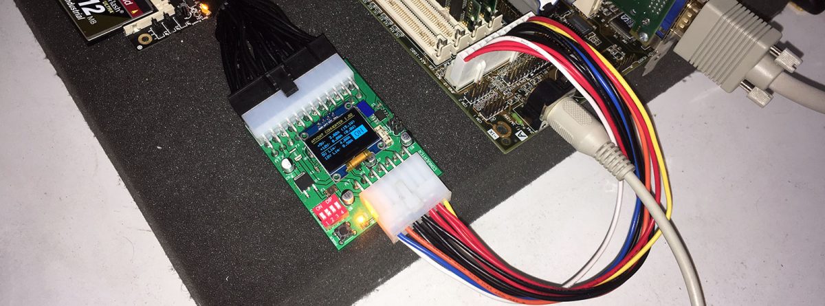
After the math, let’s check in real world:
As you can see, the actual load on -5V is only ~6 mA. This is a low current, but it’s required to get sound. As soon as I disconnected the -5V line, the sound card stops working.
Preamplifiers are very sensitive to electric noise. For such low current requirement, a DC-DC converter is useless and even harmful to sound quality.
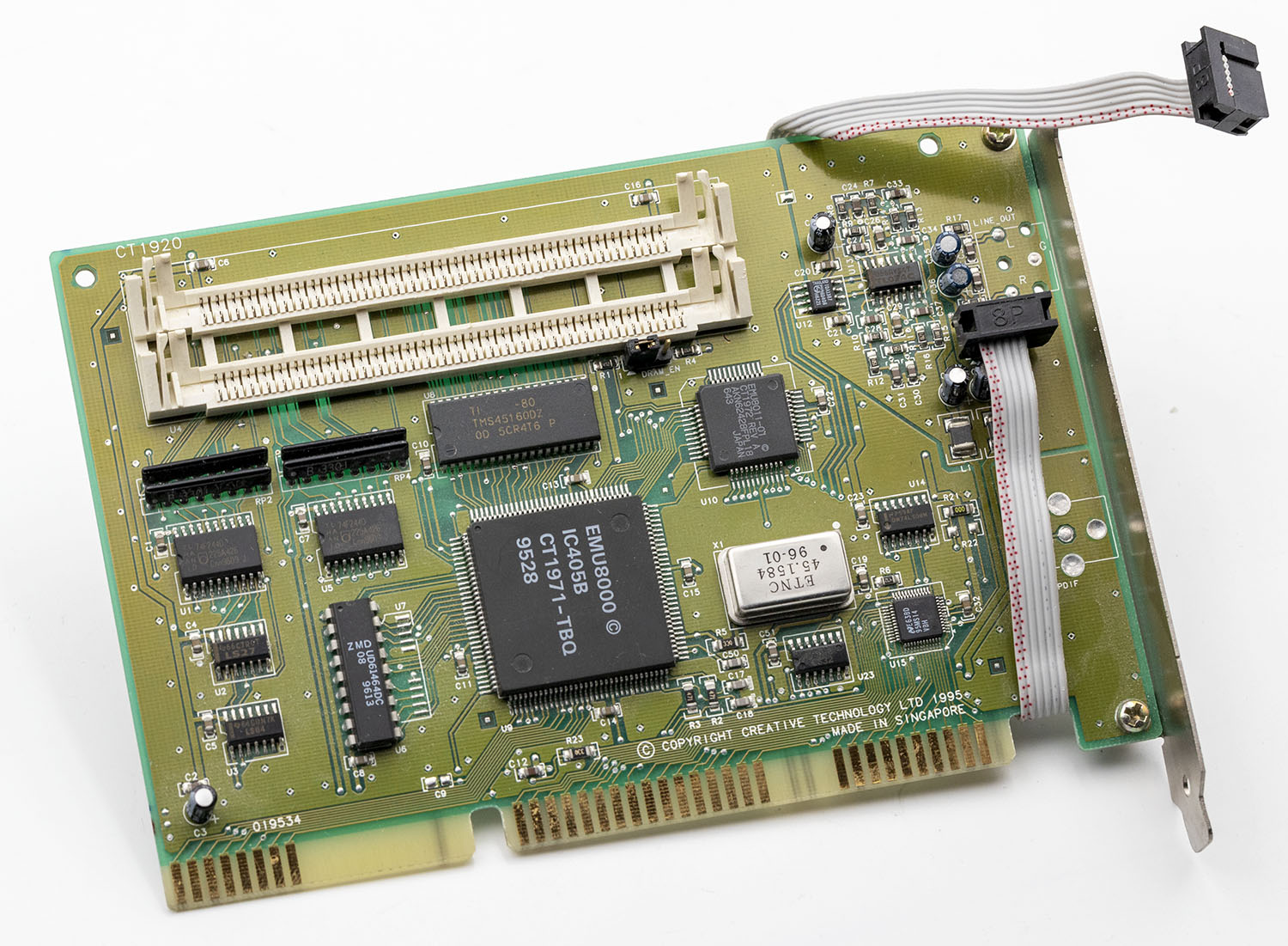
The same schematic is found on all sound cards that requires -5V. Here is a Sound Blaster CT1920 AWE Upgrade “Goldfinch”: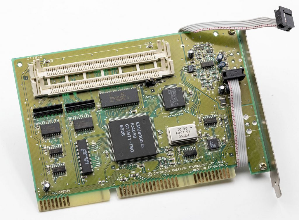 The -5V line is also used for the TL074C quad opamp (very similar to the KA3403) and outputs only a low power “Line Out” Signal. I measured the typical current slightly below 10 mA.
Finally, you probably wonder what’s the point with other ISA cards that are NOT sound cards. Short answer: same! None of them requires more than a few milliamps on -5V. For example, here is one of the rare ISA Network cards that needs -5V to work properly, the 3COM Etherlink 16 TV (3C507-TP) :
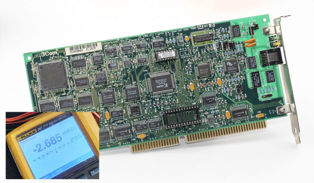 Connected to an Ethernet 10Base-T switch, it only requires 2.5 mA on -5V.
Conclusion: the maximum current required on -5V is very low and we need a voltage with low noise because it is usually used to fed preamplifiers. A linear regulator is definitely the way to go. On the ATX2AT Smart Converter, you will find a linear regulator protected with a 100 mA resettable PPTC fuse.