SUCCESSFULLY FUNDED ON KICKSTARTER!
TL;DR – The ATX2AT Smart Converter is the ultimate tool to securely replace vintage power supplies with a standard PC ATX power supply. It’s open-source, open-hardware and firmware upgradable via USB.
|
MENU |
What is it? – A useful tool for everyone serious about retrocomputing!
The ATX2AT Smart Converter plugs on a standard 24-pin ATX PC Power Supply and acts as an intelligent protection device for old retro-hardware. It can be seen as a couple of programmable fuses with monitoring capabilities. You can set the current limits and define how quickly it will react to an overpower condition. It was originally designed for vintage PCs (with AT-Style power supply), but it can also work with old Macintosh as well as many other 70s/80s/90s computers, consoles, etc.
The ATX2AT Smart Converter is dedicated to anyone who repairs or just want to protect their precious old hardware from disasters. It offers much more advanced and useful capacities than a standard passive adapter cable.
Here is a description of the integrated features:
-
- +5V/+12V Programmable Over-Current Protection: Almost all pre-Socket 5 motherboard (from 8088 to early Pentium) drawn 90% of their power on +5V. But there is also some dramatic failures on the +12V rail, finding its way to the +5V and burning everything. The ATX2AT Smart Converter monitors the current drawn on both rail in real time. 8 different limits can be set with the dip switches. For example, 486 boards usually work fine with the default settings: 4.00A max for +5V and 500 mA (0.5A) for +12V. But you can also choose 1.50A/0.20A or up to 8A/4.75A.
 |
 |
-
- Configurable reaction time: both integrated “virtual fuses” can act as slow-blow or extremely fast-acting fuses. At 150 ms (still much faster than you), the “slow” option is usually enough to prevent any damage without false-positive triggering, but sometimes, the ultra-fast option may be useful. We’ll discuss that later.
- Integrated -5V Converter: the ATX2AT Smart Converter uses a 79M05 regulator to generate the missing -5V rail on modern ATX power supplies. It can be used with your nice AWE32 Upgrade Card or any other card that requires -5V.
- -12V/-5V Protection: Negative voltages are sometimes used by some old extension cards and may also fail. Two PTC (resettable fuses) prevent damage in case of shorts on negative rails (100 mA on -5V and 500 mA on -12V).
- Onboard MOSFET: PSU are sometimes slow to react to a shut down order. Moreover, even after they stop supplying power, their massive output capacitors can still discharge and make the damage worse. The ATX2AT Smart Converter integrates massive power MOSFETs able to cut the power by itself, without relying on the PSU.
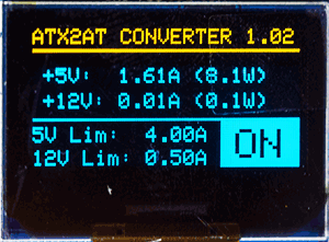
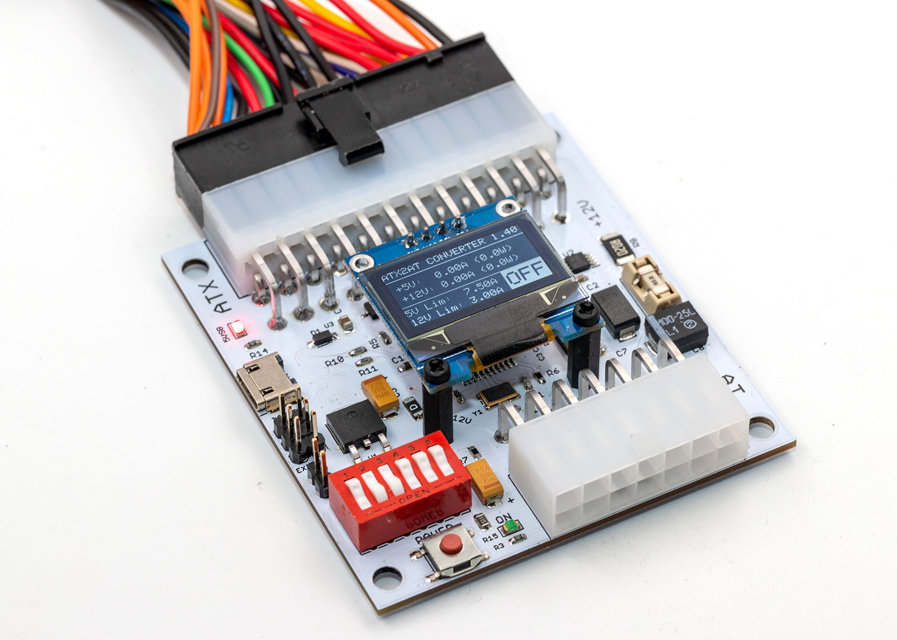
- Current monitoring: real-time current monitoring is displayed on a small 0.96″ OLED display. It also shows the actual current limits and warn you if an overcurrent is detected (also telling on which rail it occurred). The overall precision is ~2%. The PCB includes a 0.5% voltage reference.
- Failure-proof: sh*t happens! If, for some very unlikely reasons, the embedded micro-controller or the current sensor fails, the ATX2AT Smart Converter also includes two very fast acting fuses (10A on +5V and 5A on +12V) as a last-resort protection. They’re mounted on fuse holders and are easy to replace if needed.
- Current filtering: All four power rails are filtered with long life & low ripple tantalum capacitors.
- Versatile: Outputs are located on a common 14-pins Molex MINI-FIT connector (same family than the 24-pin ATX connector). You can easily build your own cable to power other retro-hardware.
- Firmware Upgradeable: the ATX2AT Smart Converter uses a standard MicroUSB connector and its firmware can be easily updated without special equipment. It uses the standard Arduino bootloader and can be used with the Arduino IDE.
- Open-Source/Open-Hardware: Schematics, PCB Gerbers and firmware source code are available on Git.
- Configurable reaction time: both integrated “virtual fuses” can act as slow-blow or extremely fast-acting fuses. At 150 ms (still much faster than you), the “slow” option is usually enough to prevent any damage without false-positive triggering, but sometimes, the ultra-fast option may be useful. We’ll discuss that later.
Of course, you also have a push button to cycle the power (a header is also available for an external button) and a status LED. Even the PWR_GOOD signal is current-limited to prevent damage to the ATX2AT Converter in case of failure. Also note that the converter is powered with the 5VSB (Standby) signal from the ATX PSU, so it works even if the PSU is not started.
What’s the story behind this tool? – And why do you need one…
In summer 2018, I finally decided to check a lot of old 286/386/486 motherboards laying on my desk for years. These boards used to be available for a few bucks on eBay, but they’re now outrageously expensive (decent 486 motherboard are now selling for $100 and sometimes much more). Thanks to the retro-computing gossip! My motherboards, as often, came in “unknown” condition from a local seller and. After a first (quick) visual check, I tried to power them with a known-good CPU (and some already tested FPM SIMMs).
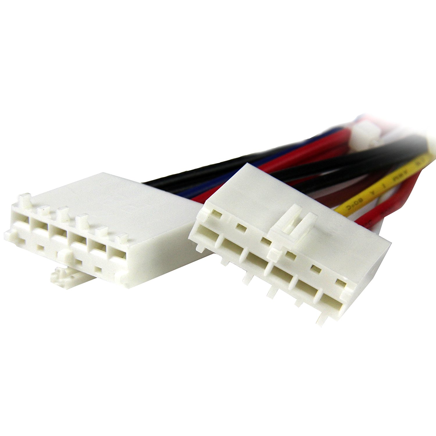
Back in these days (from the original IBM PC circa 1981 to the mid/late ’90), “AT” boards were powered via the infamous P8/P9 connectors. Like many other old-junk addicts, I used a standard passive ATX to AT adapter (available everywhere for ~$5) with a modern ATX PSU. At first sight, the only real drawback of these cheap adapter is their lack of -5V. ATX power-supply doesn’t output that negative voltage, but it’s not really a big deal: -5V was only used for some ISA boards. The famous Sound Blaster 2.0 (CT-1350B) from Creative Labs, as well as Roland LAPC-I and 3Com Etherlink 16 TP, being the most popular ISA extension boards that require -5V.
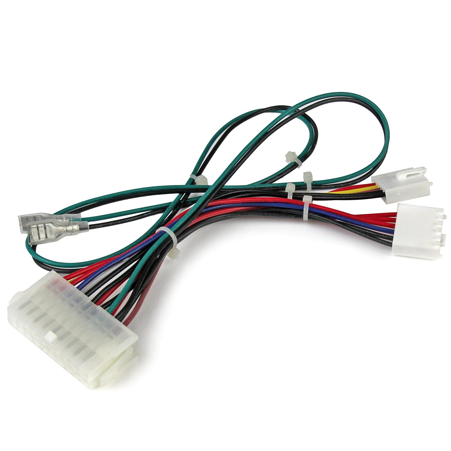
Two kinds of ATX to AT adapters are available on the market for a few bucks: the cheapest ones have a built-in strap to ground the PWR_ON signal. As soon as you plug the adapter, no matter what’s connected or not, it will start the ATX PSU. To power on/off the whole platform, you must use the main switch. Other adapters come with a (usually bulky) switch to trigger the PWR_ON signal. That’s better because if something goes wrong, the current from the PSU can be stopped much faster. Unfortunately, none of them protect your precious historic hardware if something goes wrong.
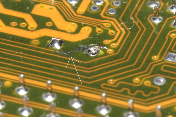
But let’s go back to my old motherboards. The first one was a nice 486 PCI board, powered by a SiS chipset. I connected everything for the first run and flipped the switch on my ATX to AT adapter. After about 3-4 seconds, I heard a sinister crackling noise and immediately switched off everything. Too late: magic smoke came out from a tantalum cap. I removed everything and carefully checked the damage. The board was FUBAR: two caps almost totally destroyed and, much more serious issue, I had two burnt PCB traces on the back side. I would realize later that a voltage regulator was also destroyed in the process. Unfortunately, my 486 DX4-100 died. It seems the 3.45V regulator was bypassed and the CPU received 5V for some seconds. Both SIMMs survived, but I raged quite a bit and it was time to do something about that.
The root cause of all these damages was the time needed to react. When you ear cracking noise, it’s already way too late. The problem got even worse because of the tremendous power that a modern ATX PSU can deliver: up to 20A on each rail, and often much more. And you can’t count on the integrated overcurrent limitation. The power drawn by an average 486 motherboard is less than 2.5A. If something fails and creates a short with a low resistance (let’s say 0.25 Ohm, that’s really small, almost short), the PSU will continue to deliver 20A without shutting down on overcurrent condition. Enough to burn small PCB traces in less than a second.
Adding a couple fast-acting fuses on the +5V/+12V power rails directly on the cables could be a good solution … but it’s not. First because the “fast-acting” is not really THAT fast, then because you will burn a lot of fuses if you need to fix a board, and finally because there is a big gap in power consumption between a 386SX motherboard and a Socket 4 (Pentium 60) AT board. You don’t want to spend your time messing with the fuses, right? Right. To solve these issues, protect your old hardware and help anyone that who wants to repair vintage boards, we now have the solution: the ATX2AT Smart Converter.
You may think that the faster a fuse acts, the better the protection. Well, not really. On an unpowered board, you’ll find a lot of discharged bypass capacitors. As soon as power is first applied, these capacitors will charge all simultaneously, and acts, for a very short time, as shorts, causing a temporary spike in current consumption. If your fuse is too fast, it will blow because of the very quick overload. The same is true for motors (or a CPU fan), which generated a large peak when they start. To prevent false-triggering, the ATX2AT Converter in SLOW BLOW mode will allow a grace period while the power can be reach +125% of the set limit (but not more than 9A in any case). Let’s see that :
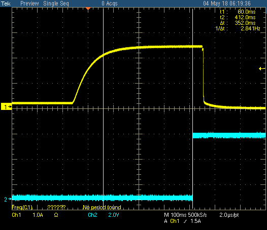
This capture show the ATX2AT Smart Converter, configured in the default SLOW BLOW mode with a 1.5A max current limit, connected to an electronic load. The load is then switched from 0.2A to 2.5A. The “grace period” is fixed at 350 ms, then the power is switched off by the micro-controller. This value is set arbitrary and may be changed with a firmware update.
But sometimes, you want a REALLY fast acting protection. For example, on a fragile low-power motherboard. You can set the FAST BLOW mode, which activate almost immediately :
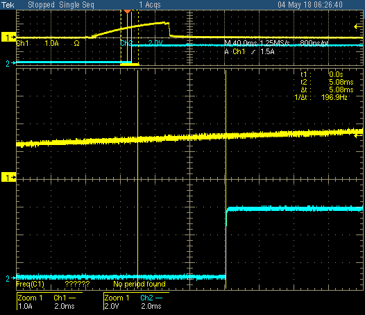
In FAST BLOW Mode, the average reaction time is ~5 ms. The OLED display refresh rate is lowered to one time every 5 seconds to let the MCU react as fast as possible. Keep in mind that, after the power down signal is sent, the PSU should react. On my Seasonic Focus+ 550W, it needs ~10 ms, so the whole process between the detected overcurrent condition and the actual power being switched off is ~15 ms. That’s extremely quick and unlikely to cause any damage, even on very sensitive components.
If you wonder if you should use the FAST BLOW Mode, answer is simple: you shouldn’t. And here is why. Both the previous captures were done with lab equipment and an electronic load. In real-world condition, the current peak on failure is usually way bigger, with a much more aggressive ramp time. I tried a suicide run with a working board and a 486 DX2-66 wrongly plugged (180° reverse) in the Socket 3. Here is the screenshot in SLOW BLOW Mode :
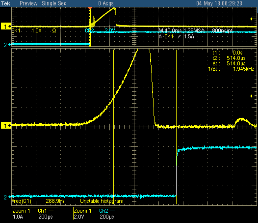
With a strong failure, the +125% absolute limit of the SLOW BLOW Mode triggers almost instantly (in about 500 µs). Good news : both the motherboard and the CPU survived. Tried 10 times in a row…
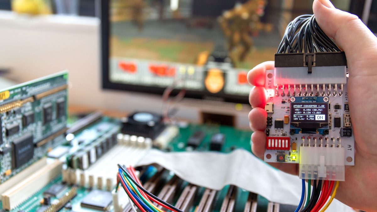
Now we want to see it in action! – Fine !
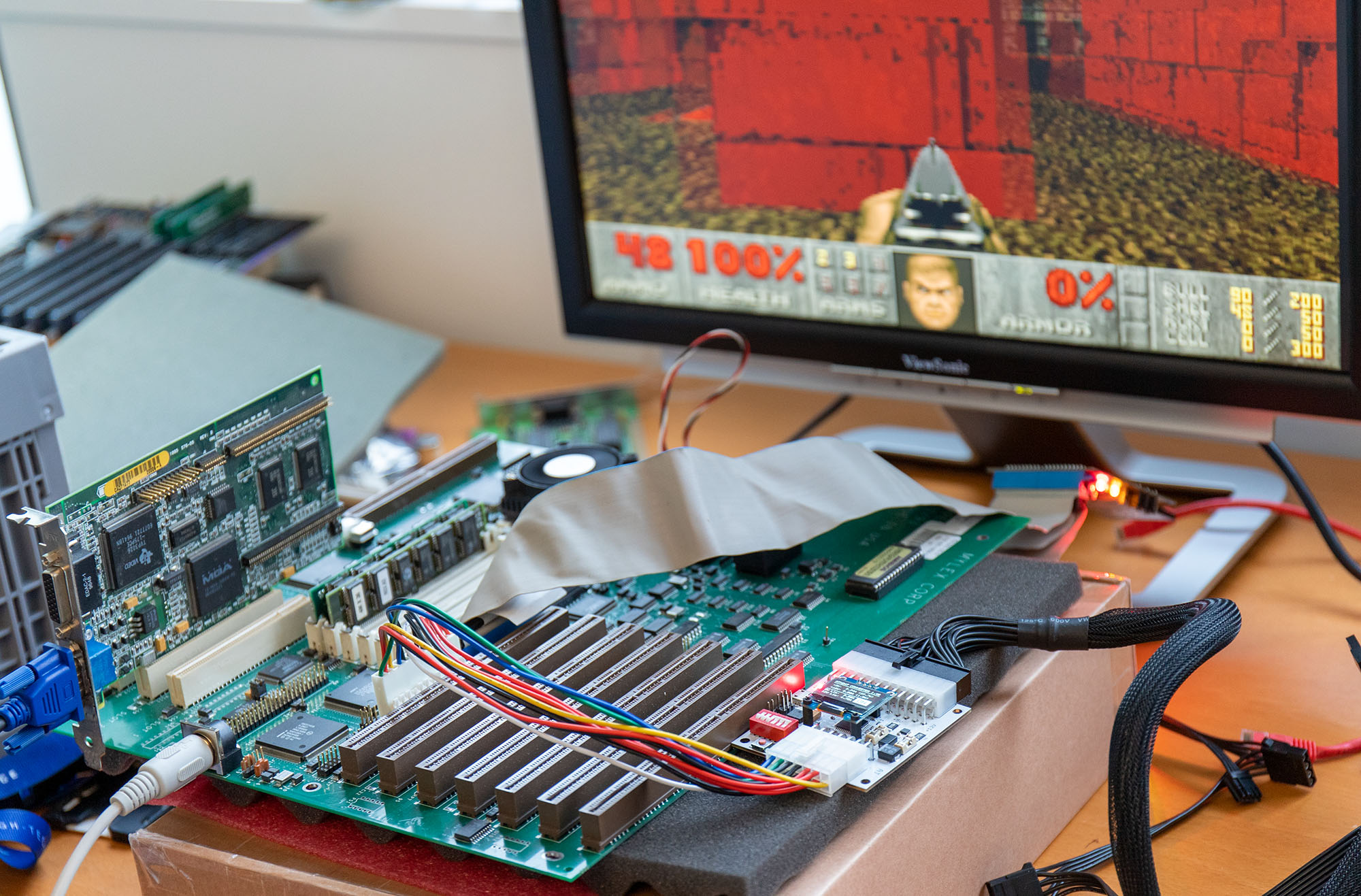
Here is the final ATX2AT Smart Converter in action
Here is an early prototype of the ATX2AT Smart Converter running on a 486 board.
The ATX2AT Smart Converter has been tested working on all AT PC board, from the original IBM PC 5150 motherboard (w/ Intel 8088 CPU) to the latest massive EISA/PCI Socket 4 motherboards (w/ Pentium 60-66 MHz) :
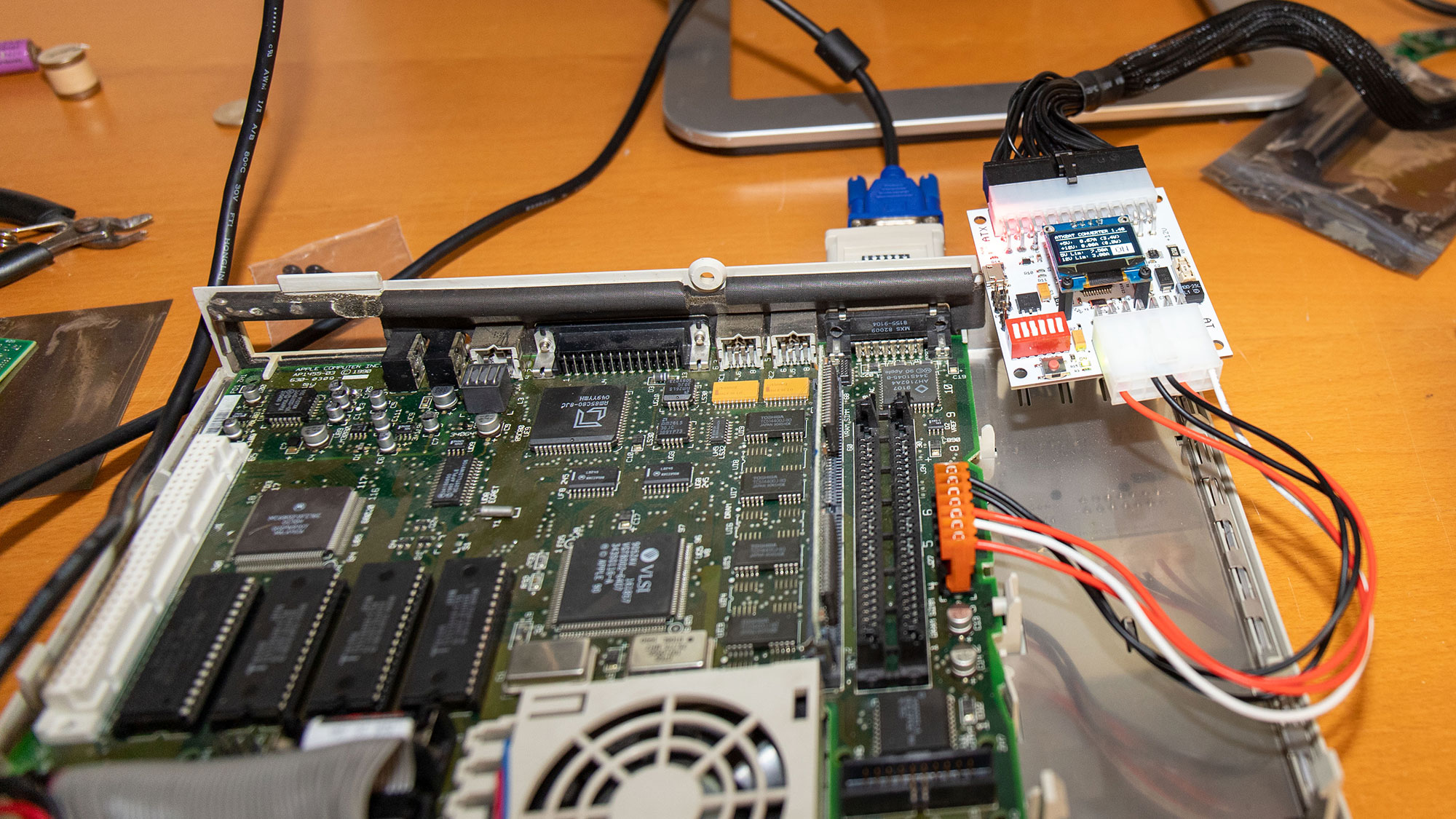
 It was also tested successfully on non-PC hardware, like a Apple Macintosh LC that came with a defective power supply. The only thing needed was a custom cable :
You just received your ATX2AT Smart Converter? Nice! Hope you’ll like it!
Basically, you just have to plug the 24 pins ATX connector from your ATX PSU and the AT cable to your AT motherboard, then push the button to make it live. Here are some important tips&tricks to make good use of the ATX2AT Smart Converter :
-
-
- Choose a decent ATX PSU – Don’t use an El cheapo (c) ATX PSU. The quality of the current delivered is often awful. Filtering capacitors are integrated into the ATX2AT Smart Converter, but they can’t do miracles if the current supplied is full of noise and ripple. The Seasonic “Focus” line is a great choice, but there is plenty of other good quality PSUs on the market.
- Choose the right power rating – Even if the ATX2AT Smart Converter has been tested on a Corsair 1200W PSU, it’s not recommended to use an ATX PSU rated more than 550W to avoid giant inrush current in case of failure.
- Select the correct settings – As with all protection device, it’s very important to size the current limiters correctly to offer the best protection. For everything up to 386s, a limit set around 2.5A for +5V and 500 mA for +12V is often the best choice. Some 486s motherboard requires up to 4.5A on +5V and some Socket 4/5/7 (Pentium) platforms could need up to 6.5A.
- AT Connectors fitting – The P8/P9 connectors are true AT P8/P9 connectors and not standard Molex KK 3.96mm connectors. The difference is the plastic locking clips, only present on AT connectors. The mating is extremely strong, and you have to push quite hard to plug it. It’s often great for a fixed setup, but if you use the ATX2AT Smart Converter as a testing/debugging tool (with frequent mating/unmating cycles), I highly recommend cutting off some of these plastic clips (at least the longer ones, on red on the schematic below).
 Some AT boards with non-standard connectors also require having them removed to mate correctly. I considered cutting these off by default before shipping, but it’s probably better to let you choose as they’re very easy to remove with pliers or cutter.
- Choose a decent ATX PSU – Don’t use an El cheapo (c) ATX PSU. The quality of the current delivered is often awful. Filtering capacitors are integrated into the ATX2AT Smart Converter, but they can’t do miracles if the current supplied is full of noise and ripple. The Seasonic “Focus” line is a great choice, but there is plenty of other good quality PSUs on the market.
- Avoid overloading – If you intend to use the ATX2AT Smart Converter for something unrelated with x86, please take care about maximum current limits. Drawing more than 6A on +5V requires some decent airflow around the converter. -12V should be limited to 400 mA and -5V to 50 mA (as the -5V linear converter can dissipate a lot of heat). In real-world application on PC, the power consumption on negative rails never exceeds 20 mA for -5V and 75 mA on -12V.
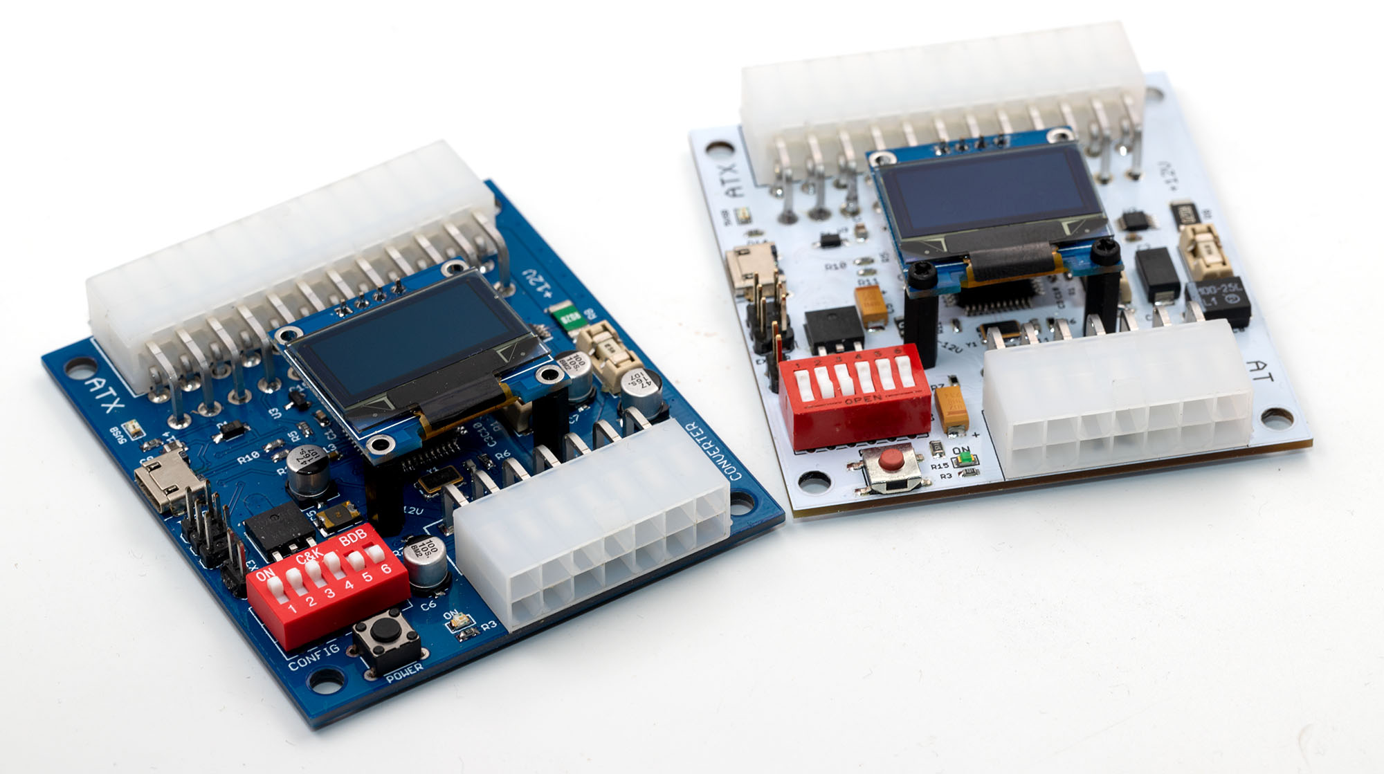
Configuration Settings – DIP Switch ’em all
– WORK IN PROGRESS – I will update this page with a more visual configuration settings soon.
The ATX2AT Smart Converter contains a 6-way DIP Switch.
The first three switches (labelled 1-2-3) set the current limit for +5V and the next two (4-5) set the current limit for +12V :
SW1-SW2-SW3
OFF-OFF-OFF
OFF-OFF-ON
OFF-ON-OFF
OFF-ON-ON
ON-OFF-OFF
ON-OFF-ON
ON-ON-OFF
ON-ON-ONMax +5V Current
4.00 A
1.00 A
2.25 A
3.25 A
4.75 A
5.50 A
6.75 A
8.00 ASW4-SW5
OFF-OFF
OFF-ON
ON-OFF
ON-ONMax +12V Current
0.50 A
1.50 A
3.00 A
4.75 AThe last switch (6) enables the fastblow mode when enabled. This mode is only for development or advanced debugging as it will trigger almost instantly on any system.
The ATX2AT Smart Converter is an Open-Source, Open-Hardware project. All files (including BOM, PCB Gerbers, etc.) are available on the official GitHub repo.
When plugged in a USB port, the ATX2AT Smart Converter is detected as a Arduino Micro. The shipping firmware is v1.13 and the source code can be downloaded here.
An early beta of the companion tool is also available (and its C# source as well). Precompiled binary for Windows 10 64-bit is available here.
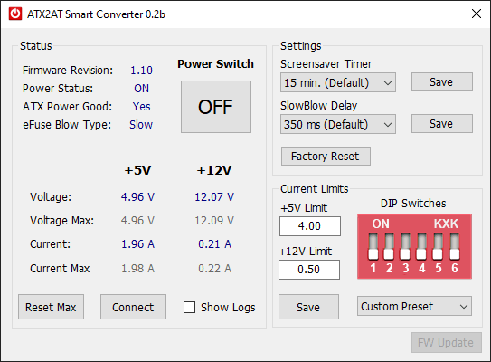 The Companion Tool offers real-time control & monitoring and configuration of various options (screensaver timer, SlowBlow Delay, Current Limits for each slow, etc.). It’s still an early beta version but additional features will follow soon. Feel free to contribute on GitHub!
There is some spares remaining from the Kickstarter campaign, but they will not be sold until all rewards are shipped. Price will be €49 + shipping (€5 to France, €10 worldwide)
-