I’ve just released a new firmware (1.21) for the ATX2AT Smart Converter and an update (0.4b) for the Windows companion tool (ATX2AT Configuration tool). Both are available as source and binary on the GitHub page.
Here is the change log :
-
- Added a configuration option for AT-Style push button
- Added a “firmware outdated” version check at startup
- Added a firmware update feature within the Configuration tool for easy update
- Solved an issue with Infinite (disabled) screensaver setting
- Solved an issue with log display
Basically, you just need to download the ATX2AT Configuration tool v0.4b binary package and use the “FW Update” button located on bottom-right corner. The tool should be able to auto-detect the ATX2AT Smart Converter, switch it to bootloader mode then use the embedded avrdude to flash the new firmware. If all goes well, you will see your new Firmware Revision as 1.21 :
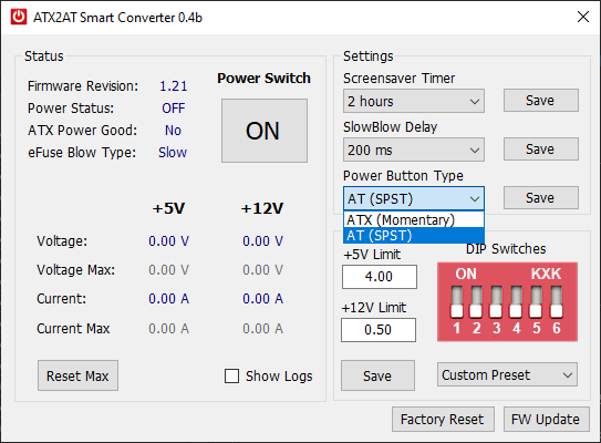
You will notice a new option called “Power Button Type” that defaults to the standard ATX-style (momentary push button). Some users asked for a way to use the ATX2AT Smart Converter with a genuine AT case using the standard switch (SPST). So here it is. With the Power Button Type set to “AT”, it’s now possible to wire a standard AT button on the 2-pin EXT_PWR connector (2.54 mm / 0.1″ header).
Will you be selling the spares any time soon? I only learned of this project after the kickstarter finished and would love one of these to work on my retro computers.
How much current do you recommend for socket 7 board(with pentium 120~150)?
I have some socket 5/7 board, all of the things are shown as 5v overcurrent though I set 8A for 5V.
Is anyone else having issues with the app crashing under Windows 10? I get the following when I run it:
“Unhandled exception has occurred in your application. If you click Continue, the application will ignore this error and attempt to continue. If you click Quit, the application will close immediately.
The port is closed.”
It doesn’t seem to matter if the USB cable is connected to the ATX2AT or not, or if I run it as administrator or not.
Can you please upload a screenshot somewhere?
I’m South Korean
486 PC in use for reliable power
atx2at smart converter 을
I’d like to buy it.
Thank you8!!
Some of them will be available from the US by the end of June. I’m looking for solutions for new batches.
Hi~
I am using a Pentium PC.
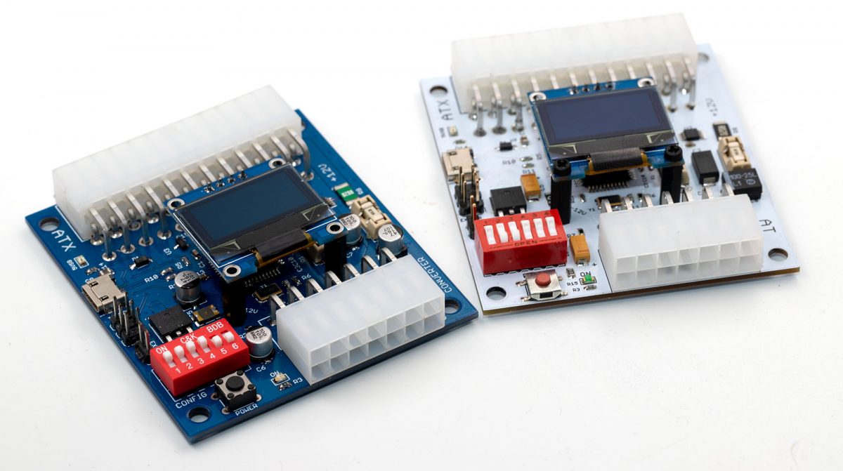
I built an ATX2AT Smart Converter using the BOM and PCB Gerber files you shared.
When I first supplied power after building the board, it appeared to be working normally.
Afterward, I connected it to the motherboard and turned on the power.
An overcurrent occurred.
I made another one, but the same symptoms appear.
When no load is connected, it displays like this:
+5V: 0.00A (7.92V)
+12V: 0.00A (17.44V)
I would like to know if this is normal.
The voltage reading are wrong, that usually means calibration factors are not set (0x00).
Write them at 0x80 if you don’t have proper calibration equipment.
Thank you for your reply.
While making this, I thought I might have done it incorrectly and was unable to regain my composure for a while.
So, I have a question.
Should I have uploaded fw112.elf and fw112.hex first?
I had compiled and uploaded ATX2AT.ino to an Arduino Leonardo board.
After that, I extracted the 32u4 IC and attached it to the ATX2AT board.
Come to think of it, I suspect that this method of operation might have been the cause.
I will try modifying it and reply if I find anything unusual.
Thank you.
1. I uploaded the fw112.elf file to the chip.
2. The voltage was displayed correctly.
3. I pressed the power button. Over Current is still displayed.
4. I would like to know the detailed method for recording the calibration factor you mentioned.
Please help me.
I know it is a hassle, but I ask for your help.
The problem has been resolved.
1. I turned on the power after short-circuiting resistors R8 and R9.
No overcurrent occurred.
2. I turned on the power after removing the short circuit between resistors R8 and R9.
No overcurrent occurred.
Afterward, the voltage and current measurements are normal.
I do not know why this method resolved the issue.